
KEY Thermal Testing Test Profiles
If you reside in a place like Silicon Valley, where the sun is always shining, rain is rare and snow is a foreign concept, this post may be hard to relate to. But here in Toronto, our vehicles are subjected to nearly +35°C (95°F) with high humidity in July, dropping to -25°C (-13°F) with a wind chill in January. The subsystems, components, lubricants and coolants all have to withstand and perform under these dramatic extremes.
As extreme as the ambient temperature may be, vehicles need to reach an optimum operating temperature for efficiency and emissions. Regardless of the outside temperatures, the engine will heavily influence the temperatures of the components in and around it. This can cause significant thermal stress, as ramp rates are increased to reach target temperatures as soon as possible.

Our mechanical oil pump test system, Ensure mOP™.
Testing
Due to elevated operating and ambient temperatures of various automotive powertrain systems, environmental thermal testing is crucial for guaranteeing product quality and reliability. Automotive components typically need to be verified at both the cold and hot extremes, as well as transition between those extremes, which usually translates to test temperatures ranging from -40°C to +150°C.
An additional test requirement also involves thermal fatigue analysis. This type of testing is intended to pinpoint any weak spots in component design, such as mismatches in coefficients of thermal expansion between dissimilar materials, and the resultant fatigue stresses, or in more extreme cases phenomenons such as structural warpage.
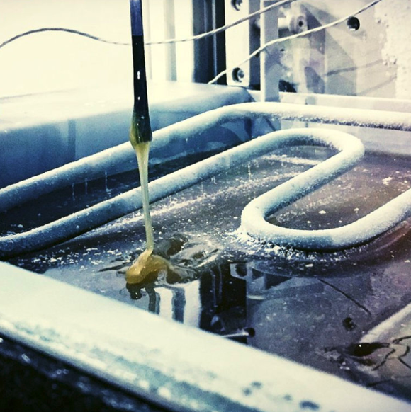
Oil at -40c
Rapid-cold temperature testing on one of our Ensure mOP™ test systems using our Horai™ technology.
The section below describes a set of five different tests which are used to benchmark the capability of the component to withstand some of these thermal stimuli.
Low Temperature Wakeup (as per IEC 60068-2-1, Test Ab, Cold)

Intention of this test is to simulate extremely cold temperatures, as if leaving a vehicle outside overnight during an extremely cold night.
This test is used to verify the ability of the component to function after extended exposure to a low-temperature extreme (Tmin).
The test sample is evaluated for proper functionality at room temperature and nominal supply voltage. The sample is then soaked at ambient temperature Tmin for a specified period of time (usually 24 hours), with the electrical wiring harness still connected and supply voltage set to zero. After the soak period, and while still exposed to Tmin, the component is turned on and evaluated for proper functionality.
High Temperature Degradation (as per ISO 16750-4, High-Temperature Tests, Operation)
This test is used to verify the ability of the component to function during extended exposure to high temperature (Tmax).
The test sample is evaluated for proper functionality at room temperature and nominal supply voltage. The sample is then heated to ambient temperature Tmax and soaked at this temperature for a specified period of time (usually at least 500 hours). The electrical wiring harness is still connected, and the supply voltage kept at nominal.
The test sample is cycled through functional operation representative of normal usage, monitoring for any degradation in performance or failure. The supply voltage can be changed from nominal to either the minimum and/or maximum values for specified portions of the test.
Vibration with Thermal Cycling (as per IEC 60068-2-64, Test Fh, Vibration, Broad-Band Random (Digital Control) and Guidance)
This test is used to verify the ability of the component to withstand vibrations that would normally occur in field conditions.
The test sample is evaluated for vibration in all three principal axes (X, Y, Z) sequentially. A random vibration test is used to capture behavior starting from the low-end frequency spectrum (i.e. road induced), up to the high-end frequency spectrum (i.e. engine component induced). This range is usually covered by a frequency range of 10 - 2,000 Hz, with a particular power spectral density (G2/Hz) at specific nominal frequency values.
In conjunction to the component being vibrated, the test sample is exposed to a thermal cycle. The cycle typically ranges from Tmin and Tmax, with particular ramp rates (°C/min) and dwell times. Each thermal cycle is usually 480 minutes in duration.
Power Temperature Cycle (PTC) (as per ISO 16750-4, Temperature Cycling & IEC 60068-2-14, Test Nb, Change of Temperature)
This test is executed in conjunction with the Thermal Shock Air-to-Air (TS) to verify the ability of the component to withstand thermal fatigue and degradation due to thermal cycling.
The test sample is evaluated for proper functionality at room temperature and nominal supply voltage. The sample is then heated to ambient temperature Tmax, and allowed to dwell at that temperature for a specified period of time (usually one hour). Subsequently, the sample is cooled to an ambient temperature Tmin, and allowed to dwell at that temperature for a specified amount of time (usually the same as the heated dwell time). The heating/cooling rate of change between Tmin and Tmax can be anywhere between 2-15 °C/min.
The supply voltage can be changed from nominal to either the minimum and/or maximum values for specified portions of the test. The test sample voltage may also be set to zero during the temperature transition between Tmax and Tmin.
Thermal Shock Air-to-Air (TS) (as per ISO 16750-4, Temperature Cycling & IEC 60068-2-14, Test Na, Change of Temperature)
This test is executed in conjunction with the Power Temperature Cycle (PTC) to verify the ability of the component to withstand thermal fatigue and degradation due to thermal cycling.
Typically, a specific number of PTC and TS cycles are combined to create a full test portfolio. They are usually executed sequentially, with a functional test at specific points in between to verify the component performance.
Solutions
There are a few tools required to effectively perform thermal testing to the above requirements. At a high-level, you need:
A test bench capable of performing performance and/or durability tests, with a measurement circuit rated for the temperature extremes;
An ambient temperature control solution (i.e. thermal chamber);
A fluid temperature conditioning system for fluid/hydraulic components (i.e. chiller);
PID-tuning and software solution to automate and execute test profiles.
Typically, electronic components can be tested to these standards with a thermal chamber alone. However, as hydraulic components (i.e. pumps, heat exchangers, valves) become electrified, the electronics will be subjected to thermal stress of the fluid conducted through the body of the component.
Fluid temperature conditioning can be complex and expensive, depending on the testing requirements (i.e. cold start or low temperature wakeup, versus thermal cycling). Single component testing at cold temperatures can be easily achieved using liquid nitrogen. Large scale durability tests between -40°C to +150°C may require a multi-stage chiller system with a specialized heat transfer fluid, sized for a specific application.
For short-term testing, it might be the most cost-effective to outsource to a full-service laboratory. Depending on the component or subsystem, test facilities exist that will have test benches for characterization, thermal chambers and chillers. Our ATA Lab™ service is an example, which focuses on thermal testing of lubrication or coolant components.
HOW WE CAN HELP
Test systems to benchmark performance, durability, and end-of-line production validation
Robust fluid conditioning subsystems, engineered for prolonged use between extremes.
Accurately measure key parameters for on/off and proportional multi-port control valves.
On the control side, simulate various test conditions (i.e. hot/cold fluid and air temperature) according to industry standards
Fluidify™ is a plug-and-play rapid fluid temperature control module, Ideal for performance or durability testing of oil and coolant components
We also utilize our systems, standards, and technologies to support clients with test services
Responsive support services that range from 24/7 engineering assistance to full system calibration (meets ISO 17025 standard).
HAVE A QUESTION FOR OUR ENGINEERING TEAM?


A FLUID CONDITIONING TECHNOLOGY BUILT FOR AUTOMOTIVE
Condition oil, coolant and/or ambient air.
-40°C to +150°C (oil)
-40°C to +130°C (coolant)Up to 13°C/min (average).
Including ISO 16750, IEC 60034 and IEC 60068.
Learn more about Fluidify™
RELATED CONTENT


